Hexagon Measurement SystemsNo matter what Hexagon measurement equipment or software you use, we want to hear your ideas and suggestions on how we can improve.
Thanks for your assistance in helping us shape the future. |
|

 Change from Online / Offline
A function / icon inside PC-Dmis to change from online / offline.
Let say you have more than one program running and you switch between them and want to do a test run program by program...

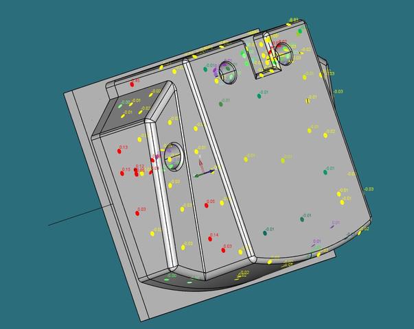
3D in reporting
Option to make 3d PDF report, based on point-cloud measurements. Same as on image, but in PDF, or something else readable by users who don't have pcdmis.. Maybe export as step model with this measured values. It's much productive to look at measurements by engineers, and it's easier to create report (for complex models) instead of cad only option.

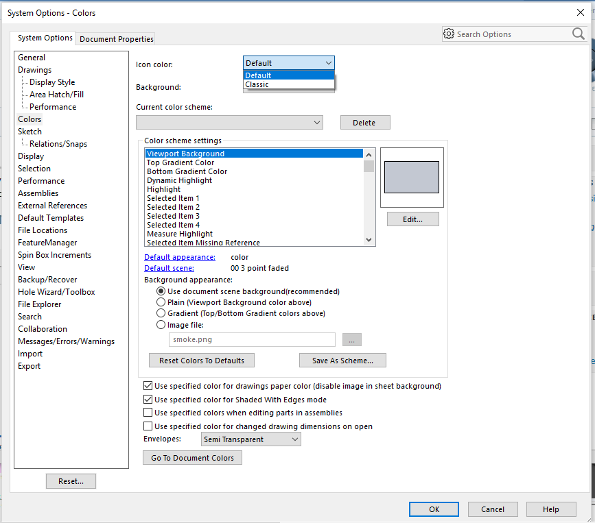
Icon Color Option
SoildWorks added a Icon color option. The option is to be able to change the Icons color from Default to Classic. Maybe they could do this with PC-DMIS to have a Icon color option.
SOILDWORKS 2016 User Interface

Have the ability to change the program from English to Metric, not just the reporting
A button that would convert the programming code from English to Metric or vice versa. If it can be done in the reporting, why can't it be done for the program itself?

Avoidance moves - using both before & after for the same feature
it would be a good idea to be able to adjust BOTH 'before' & 'after' when using avoidance moves on the same feature.for example, you might want a before distance of 40 but an after of 80.

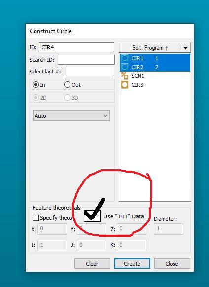
Add a "use hit data" checkbox in the CONSTRUCTION dialogue box_eliminate the need to "hardcode"
Goal with this post:
SIMPLIFY the feature construction process for things that share a centroid.
Currently:
To CONSTRUCT two or more features together that SHARE A CENTROID, one must:
1) CONSTRUCT desired features into a featureset, click OK....2) Once featureset is in the edit window, switch to COMMAND MODE and then hardcode the ".hit" / ".numhits" into the featureset...3) CONSTRUCT your final geometry out of the featureset.
This works well but is not very user friendly. Takes multiple steps & some typing, is error prone.
Workflow potential using my recommendation:
1) CONSTRUCT desired features into the geometry you need (i.e. if you're constructing two or more radii, go into circle construction..if you're constructing two or more cones, go into cone construction, etc...) & check off a box that says "Use .Hit Data" (or however you guys want to word it), click OK. (at which point the software will do the hardcoding for us and insert the code into the edit window...eliminating a LOT of typing/copying and pasting that A LOT of us do on a daily basis).
Could look something like this:
Software would directly make this code or something similar:
[code]
CIR1 =FEAT/CONTACT/CIRCLE/DEFAULT,CARTESIAN,IN,LEAST_SQR
THEO/<0,0,0>,<0,0,1>,2.3622
ACTL/<0,0,0>,<0,0,1>,2.3622
TARG/<0,0,0>,<0,0,1>
START ANG=0,END ANG=180
ANGLE VEC=<1,0,0>
DIRECTION=CCW
SHOW FEATURE PARAMETERS=NO
SHOW CONTACT PARAMETERS=NO
CIR2 =FEAT/CONTACT/CIRCLE/DEFAULT,CARTESIAN,IN,LEAST_SQR
THEO/<0,0,0>,<0,0,1>,2.3622
ACTL/<0,0,0>,<0,0,1>,2.3622
TARG/<0,0,0>,<0,0,1>
START ANG=180,END ANG=0
ANGLE VEC=<1,0,0>
DIRECTION=CCW
SHOW FEATURE PARAMETERS=NO
SHOW CONTACT PARAMETERS=NO
CIR3 =FEAT/CIRCLE,CARTESIAN,IN,LEAST_SQR,NO
THEO/<0,0,0>,<0,0,1>,2.3622
ACTL/<0,0,0>,<0,0,1>,2.3622
CONSTR/CIRCLE,BF,2D,CIR1.HIT[1..CIR1.NUMHITS],CIR2.HIT[1..CIR2.NUMHITS],,
OUTLIER_REMOVAL/OFF,3
FILTER/OFF,UPR=0
[/code]

PMI/MDB/GD&T for Native Autodesk Inventor CAD FILES in PC-DMIS
Adding the functionality of AUTODESK INVENTOR CAD files to generate de program in PC-DMIS using PMI/MDB/GD&T like CAD files from CATIA

Probe Head rotation - collision avoidance into machine bridge legs
When calibrating a longer probe, have PCDmis automatically avoid colliding with the bridge support legs of the frame when indexing for the next angle. Although you can specify the order of calibration, it would be a nice feature to have the machine alarm or automatically avoid this collision in the first place.

Add Option to Construct a Max/MIn Point From a Scan or Constructed curve
Need to add a construct Max/MIN Point option which can be either be Max Or Min point from an input scan or constructed curve. A lot of customers need to find the highest or lowest point from a scan and the current method of using the MAX or MININDEX to get the scan point number and then constructing a generic or cast point is tiresome. The user should be able to pick a scan or curve, select which axis (based on current alignment) either X or Y or Z and indeed Polar radial for 2D max/min or 3D Max/Min from the current origin.
For example to find the max polar value the user needs to know the syntax below, the software should do this for us.
ASSIGN/POLAR_ARRAY=ABS(SQRT((FINDHEX.HIT[1..FINDHEX.NUMHITS].X^2+FINDHEX.HIT[1..FINDHEX.NUMHITS].Y^2)))
ASSIGN/MAX_PT=MAXINDEX(POLAR_ARRAY)
HEX_CORNER =FEAT/POINT,CARTESIAN,NO
THEO/<0.276,2.287,-4.003>,<-0.0677693,-0.997701,0>
ACTL/<1.914,1.322,-4.004>,<-0.4452459,-0.8954083,0>
CONSTR/POINT,CAST,FINDHEX.HIT[MAX_PT]
This option could also be used for constructing a point from other features such as a plane to then report the XYZ location of the highest/lowest point on the plane or any other feature in fact. etc

Add an option for hitbased construction of features
Add a checkbox to construction dialogs allowing the user to select whether or not to construct the new feature based on hits (<featurename>.HIT[1..<featurename>.NUMHITS]) or the "regular" way (centroids). This would enhance the programming experience and shave off a couple of minutes to the programming time.
Customer support service by UserEcho
