- Hexagon Measurement Systems
-
 Ideeën

+1
Min / Max point on colormap
Min / Max point on colormap is not representative to surface.
This point will "nearly" always be on the surface edge!
And this value is used when you evaluate Profile surface dimension.
If you take a look at pictures below and special on the colormap / colormap scale. 99 percent of this surface is green and orange. The Profile surface dimension value should be around 0.5 but it is 0.756 (ASME).
This because of what I believe error from the scanner.
Different ways to solve this could be:
Let the Min / Max be on a colormap "area" and not as a point.
Or an outlier filter...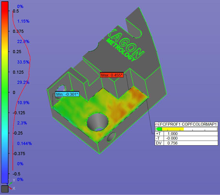
Customer support service by UserEcho

Hi @dan.brokstad. The example you show here can be easily done in PC-DMIS because it is a plane.
It becomes more difficult when the surface is curved. Currently we don't have a way to shrink back from the edges of a curved surfaced the way that we do for the plane. But we do have this planned for future development.
Hi Ute
I know about the plan option, this was just a example.
I hope for a solution on curved surface as you describe...