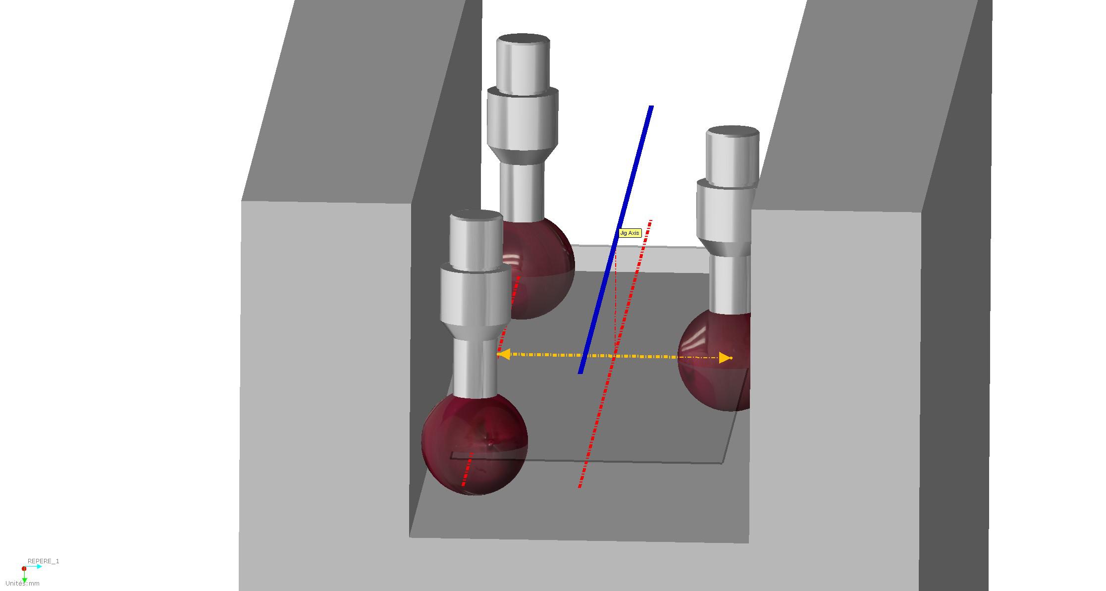
Adding a special feature to measure Jig axis from square section (3 or 4 planes)
When customers want to reverse a Tube Jig, they may face Jigs with cylindrical gates (no problem here, a simple measurement of a cilynder), but also Square gates.
For square gaes, the process is much eavier cause it requires to measure 4 (or 3) planes, construct 2 medium planes, and then make the intersection of both medium planes. In case of more than 6 axes, it becomes very heavy, boring and results in a very long program.
In GPad, we implemented a macro for such case :
- The user selects "Jig line from square gate"
- then the SW automatically asks the user ot measure 1st side plane
- then oppposite side plane
- then bottom plane
- and finally top plane
- then all the calculations are automatically done, and the user directly gets the center line.
Sometimes, only 3 planes are used (both sides and bottom plane) : then we use the side planes to calculate the "diameter" and we translate the bottom plane with half of the "diameter". then we intersect the translated bottom plane with the medium plane from side planes.
Another option to get a quick measurement (but less accurate) from 3 planes simply consist to measure 3 points:

- 2 points on one bottom edge
- 1 point on the opposite bottom edge
- From Pt 1 and 2, we make a line (from the centre the the sphere of the stylus)
- From this line and Pt 3, we calculate an intermediate "diameter" (not hte real one but the real one minus the probe diameter) and we calculate also the medium point (medium point between Pt3 and its projection onto the line
- we move the line onto the mdeium point
- we move up the line with half of the intermediate "diameter", and perpendicularly to the plane made with the 3 points.
- this gives us the axis.
Service d'assistance aux clients par UserEcho

