Hexagon Measurement SystemsNo matter what Hexagon measurement equipment or software you use, we want to hear your ideas and suggestions on how we can improve.
Thanks for your assistance in helping us shape the future. |
|

 Creation of "mirrored" points
Idea spawned from the user forum, recently from this discussion:
The longing for a function like this has been around for a long while. Basically what it should do is to create a second vectorpoint based on the vector from the first auto vectorpoint and place that second vectorpoint on the CAD surface that the first vectorpoints vector will intersect/hit. If you don't have CAD, the possibility to control the distance between the points must exist for it to be useful without CAD.
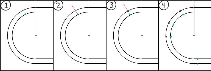
Example of using the function when measuring a groove:
(1) The function should use a "simple" auto vectorpoint as start where we place the vectorpoint at our intended position
(2) The vector of this vectorpoint is used to find the closest CAD surface along the points vector
(3) The new - or "mirrored" - vectorpoint is created on the CAD surface using the vector from the CAD surface
(4) This way we can create "perfectly" opposite points along the groove
This is not just applicable for grooves, but also for opposite planes where we want to create a plane out of the midpoints of the opposite planes - for this we need to be able to place the hits for the planes opposite each other. It is doable today, but very tedious and a function like this would ease the process.

Colour change of points selected for construction
Lets say we have a measured cad model with a load of points taken on it. These points are coloured black on the model.
For eg.
I need to create a plane using some existing points.
From the construction toolbox I choose the plane option and I select the relevant points I need to create the plane.
After selection of these points they still remain coloured black.
Is there a way to make the selected points a different colour, so as to make identification easier, that I have selected the correct points off the model?

Reference Dimensions - No Tolerance & Secondary Reporting Options
Two main attributes:
The ability to toggle tolerances off. (Basic and Reference dimensions)
The ability to have a second set of dimensional reporting options or several reporting profiles (Dimension Color Settings)
This helps with quality control. Right now, we either 'open' tolerance or don't report. There are instances where it is desirable to have values of basics and references with-out it hindering production mentality/reactions. Often I also output XYZ coordinates for In-Car and zero tolerance them, as the T-value is what's important/desired.

Increment Moves with Virtual Machine
Be able to use Increment Moves with Virtual Machine when executing paths and for collision detection.
Jog Box
CMMs need the option to have wireless jog boxes. I trip over the cord all the time and wheel over it with my chair.

Provide tolerance zone visualization
Show tolerance zone visualization with DRF animation of GDT constraints

Add a Calibration Timer that Forces Tip Calibration through Inspect
Add a Calibration Timer that Forces Tip Calibration through Inspect
PC-DMIS in one language, the report in another
I am running PC-DMIS with swedish language setting and thus, the report is also in swedish. However, it would be optimal if I could change the report template language to english - just for the report as we have customers all around the world.
In order to that today, I'd have to either run PC-DMIS in english (all the time) or change language, start PC-DMIS, open my program and print the report.
Would it be possible to add the possibility for the report templates to use a different language (other resources from the .dll's) template only for printing?

Need Square Tubing!!!!
Been begging for square tubes since TubeShaper came out. I have many customers asking for this.
Add bent tube to straight tube capabilities
I measure a lot of bent tubes with copes (fish mouth cuts) on the ends of the tubes. Would like to have the capability in TubeShaper to take a measured bent tube (with measured cylinders on each end) and convert it to a straight state with the measured end cylinders in the correct orientation. Then the straight tube can be exported as a CAD model so it can be used in a tube laser machine.
Customer support service by UserEcho
