Hexagon Measurement SystemsNo matter what Hexagon measurement equipment or software you use, we want to hear your ideas and suggestions on how we can improve.
Thanks for your assistance in helping us shape the future. |
|

 Ability to Assign a Dimension as Attribute
I would like the ability to create an attribute dimension, similar to a "Keyed In" dimension that has a non-numerical value of either "PASS" OR "FAIL" and the ability to pass that result to reports or Excel exports. Currently, all defined dimensions are numerical.

Complete autocalibration routine
Autocalibration Currently does not remeasure failed tips. My suggestion is to implement a feature within the Autocalibration routine that allows it to remeasure the tips that failed the standard deviation. As well as adding a feature within the autocalibration code that allows you to select the calibration sphere when the qualtool has been moved only. This would be used for all autocalibration within that code as well but only selected at the beginning of the program to ensure correct vector and size are used. My expectation if this gets implemented is when i leave on Friday, i can start the autocalibration routine and come back on Monday with no tips that have been outside of the standard deviations.

Gerber Format Support
The Gerber format is a standard ASCII format file structure and uses X, Y, Z and I, J, K information that enables data exchange between CAD (development) and CAM (production). It is primarily used in electronic CAD programs (EDA – Electronic Design Automation) to output layout data for printed circuit boards.
We are frequently confronted with this format and here we have a competitive disadvantage compared to providers who can read this format into their measurement software without further external conversion.
It would therefore be desirable to integrate a corresponding import interface into PC-DMIS.
Min/Max reporting for multi-times hole pattern for size and true positions
Many times we have 25 to 100 x's size and location callouts for pattern of holes. It would be nice to have PC-DMIS be able to output Min/Max GeoTol values without hard coded variable arrays.

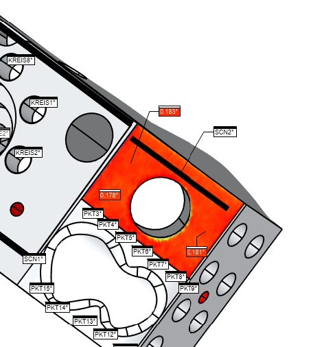
Possibility to scale the size and change the color of type of Annotation Points
As a PC-DMIS User I would like to have the possibility to enlarge the size of Annotation Points created out of Surface colormaps or Pointcloud colormaps. Sometimes it is very hard to read the value inside of Annotation Points, because they are just too small. Sometimes it is hard to read because you do not have a nice contrast between the Type and the background color. In this case it would be nice if I could change the color of the type.
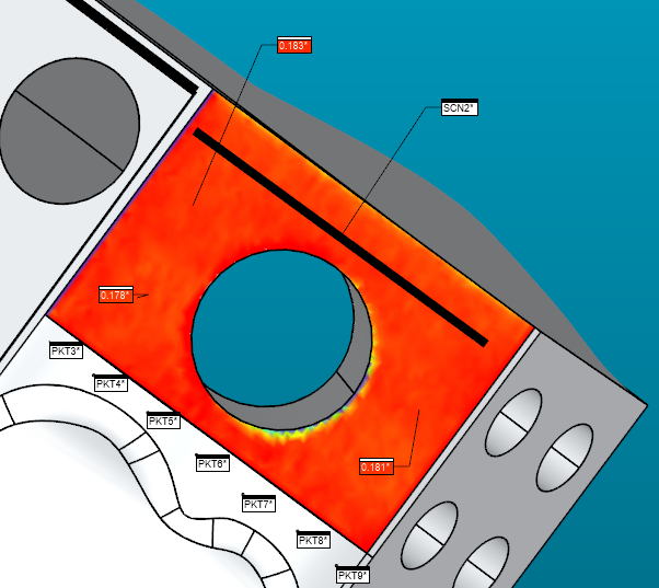
While in Graphic Window the Annotations are good to read, it may be more difficult in Reports, etc.


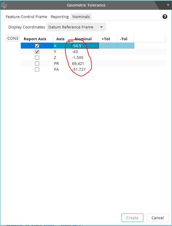
Bring back the ability to edit nominal values in Geometrical Tolerance 2020 R2
Sometimes TED from drawing not fit with model.
It was easy to edit this if necessary on Xact / Geometric Tolerance field.
Unfortunately strange decision to disable this feature in 2020R2....

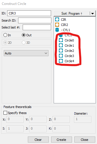
Individual features inside loops selectable in constructions and dimensions
When using loops, anything inside (such as features, dimensions, etc.) must be explicitly typed and named with the array number of the loop iteration, as shown in this example:
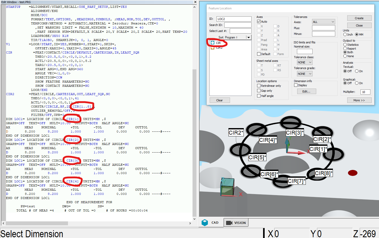
I would like to be able to select the looped features, similar to how the Auto Cylinder Concentric Scan has individual circles that can be selected. This could be based on the loop number parameters, or perhaps the loop would need to be executed to create those looped features?

Change the "Close" menu option to "Save and Quit"
Change the "Close" menu option to "Save and Quit".
This would be much more clear in what is happening.

Single click Auto circle by using star dia probe
In fixed probe head cmm if single click we pick the auto circle by using star dia probe it would be very easy to measure the circle, the same option available in quindos software .please try to implement the same in PCDMIS.
Service d'assistance aux clients par UserEcho
