Hexagon Measurement SystemsNo matter what Hexagon measurement equipment or software you use, we want to hear your ideas and suggestions on how we can improve.
Thanks for your assistance in helping us shape the future. |
|

 Allow evaluation of angularity and perpendicularity vs 3 datums and MMC/LMC modifier to said datums with ISO1101 settings
Hi PC-DMIS team and users.
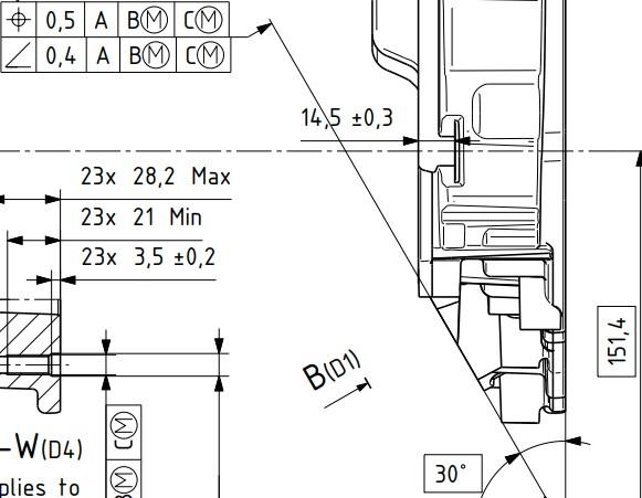
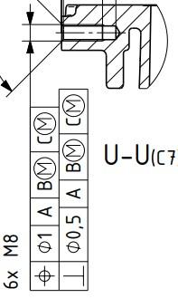
I have time to time encountered requirements that call out for angularity and perpendicularity versus 3 datums. Since PC-DMIS currently doesnt allow this, i have researched about it with my local PC-DMIS provider (Hexagon Sweden) and my employers ISO experts, who are part of the ISO committee. According to both Hexagon Sweden and the mentioned ISO experts, both perpendicularity and angularity, although not very clearly described in ISO1101 currently, are fully intended to be used with a complete datum system such as A B C, which is confirmed with the people who participated in writing the current version of ISO1101.
It is to my understanding that this would be equal to, or very similar atleast, to be using surface profile with a complete datum system but with the OZ modifier applied. This is my current workaround when i see such requirements on flat surfaces. But when the requirement applies to a bore
or a shaft, this workaround no longer works and i have no proper way to do it.
In addition to implementing a change like this, a yellow text warning, similar to the warning text to [DF] modifier could be used as soon as the 3rd datum is defined. Where the text implies that a 3rd datum for angularity and perpendicularity is not clearly described in ISO1101, and also asks the user to consider if this is really the intended requirement for the feature, or something along those lines.
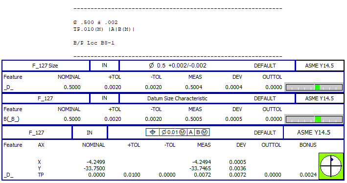
In addition to this, bring back the ability to add the LMC and MMC modifier for the datums used for the angularity/perpendicularity evaluations. There is nothing stated that prohibits this in current standards. It is allowed for surface profile with OZ modifier, so after all, why shouldn't it be allowed to be used for angularity and perpendicularity.
If you need any further clarification or explanation, im happy to fill in. Thanks!
Below are 2 example pictures from the same technical drawing.


Excel Form Report, graphical views in report
Make separate worksheets for each ANALYSISVIEW.
Include the dimension name with the graphical view, an also in the worksheet name.
And if possible in the report add a column in wich you can see the worksheet name if there is a graphical view.
This makes the step to not save everything to PDF a bit smaller.
Excel files take up less space than PDF files. And an Excel file is searchable, the PDF is not.

Add a numerical spin up/down control to the "Construct Offset Plane"
LIke title.
The numerical spin up/down would change the offset distance with x.x.
In addition to this, please display the constructed plane position in the graphics view, while changing the offset distance value so the user can see where the plane will be constructed.
Overall, I think the constructed features could do an overhaul by displaying them in the graphics window BEFORE the user clicks "Create".

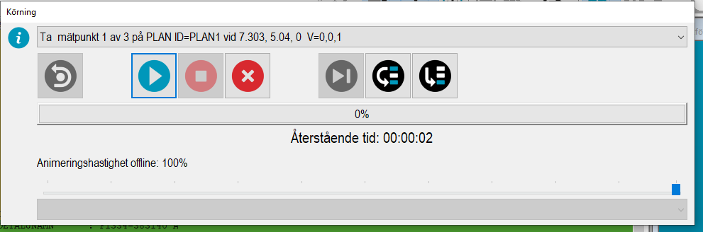
Text storlek
Skulle vilja kunna göra texten större men inte knapparna.
Svårt att se texten på lite avstånd utan att göra hela fönstret större och då blir start/stopp knapparna för stora.

Service d'assistance aux clients par UserEcho
