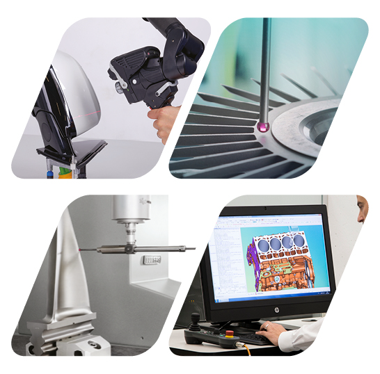
Hexagon Measurement SystemsNo matter what Hexagon measurement equipment or software you use, we want to hear your ideas and suggestions on how we can improve.
Thanks for your assistance in helping us shape the future. |
|


 Scaleable Probe Angle Grid Window
Please allow either scalable or full-screen probe angle grid window. For users with the 5 Degree and 2.5 Degree head, this will be a quality of life improvement

Precisely define the start and end point for 2D line profile
In the case of new projects, customer requirements for optical 2D line profiles are increasing. Here, we are predefined exact starting and end point. Unfortunately, with PCDMIS you can only define the start and end positions in "approximately", with the mouse. Here it would be nice if the start point and end point could be defined via a menu.

Optimize Path result window
Hi guys
I used Optimize Path in my program. Then I saw the screen with the elements with errors. It continues down the list. I wanted to pull it from the frame edge and see the rest of the list down. The list remains stable. But the framework is growing. Shouldn't I see the rest of the list when I enlarge the frame ?
Regards

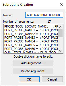
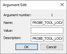
Subroutine Dialog window upgrade
Subroutine dialog windows needs a major upgrade.
These dialog windows should have the ability to change their size.
When I use dialog windows like these it makes me feel like I am going back in time. I was using my old 1995 Packard Bell computer the other day just to find these same type of dialog windows. It just made me laugh at how a software today will still have these type of dialog windows.

Multiple clearplanes
Have the ability to create multiple clearplanes and then select which clearplane to move to.
Example
CLEARP/ZPLUS#1,10,ZPLUS,0,OFF
CLEARP/ZPLUS#2,10,ZPLUS,0,OFF
CLEARP/XPLUS#1,10,ZPLUS,0,OFF
CLEARP/XPLUS#2,10,ZPLUS,0,OFF
MOVE/CLEARPLANE,ZPLUS#1
PNT1=FEAT/CONT...
MOVE/CLEARPLANE,ZPLUS#2
MOVE/CLEARPLANE,XPLUS#1
This would allow the creation of workplanes as soon as the part is "found" / datum structure is created and then select which workplane to move to at any point during the program.

Automatically exclude manual features from collision test
When running a collision test, I'd like to have the manual features ignored by default instead of having to unmark them or step through the features before DCC collision testing takes off.


Customer support service by UserEcho
