
Creation of "mirrored" points
Idea spawned from the user forum, recently from this discussion:
The longing for a function like this has been around for a long while. Basically what it should do is to create a second vectorpoint based on the vector from the first auto vectorpoint and place that second vectorpoint on the CAD surface that the first vectorpoints vector will intersect/hit. If you don't have CAD, the possibility to control the distance between the points must exist for it to be useful without CAD.
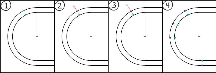
Example of using the function when measuring a groove:
(1) The function should use a "simple" auto vectorpoint as start where we place the vectorpoint at our intended position
(2) The vector of this vectorpoint is used to find the closest CAD surface along the points vector
(3) The new - or "mirrored" - vectorpoint is created on the CAD surface using the vector from the CAD surface
(4) This way we can create "perfectly" opposite points along the groove
This is not just applicable for grooves, but also for opposite planes where we want to create a plane out of the midpoints of the opposite planes - for this we need to be able to place the hits for the planes opposite each other. It is doable today, but very tedious and a function like this would ease the process.
Service d'assistance aux clients par UserEcho

I'm currently working on a project where I need to have a constant depth in a groove. Grove runs on/through non-normal surfaces, but is always normal to a working plane. I can always (unless around radii, as stated above) find a 'mirrored' point that is the 'perfect' distance - However It involves several button clicks as I am using edge points to control the depth. This would save a lot of time, even on features that are otherwise more possible.
Since this is a tight tolerance gage I am working on, around the Radii I have to set a small alignment to the feature and move to polar coordinates to find the 'perfect distance'
Got my vote.
Perhaps it could be an additional button in the existing autofeature prompts; Right near 'Find Nearest CAD Element'. Could be 'Project to nearest CAD element' and would be controlled by the surface vector for direction. Then you could toggle the direction as well.
In this instance you would:
-Create a point
(While the dialog is still open - the previous Data is persisting as normal to the next feature)
-Click in the dialog to project point in desired direction
-Adjust as necessary (I.E. Flip vector etc.... )