Hexagon Measurement SystemsNo matter what Hexagon measurement equipment or software you use, we want to hear your ideas and suggestions on how we can improve.
Thanks for your assistance in helping us shape the future. |
|

 Estimate Execute Time from Offline
As a CMM programmer, I would like to know how long real measurement will last from offline programme. Part program already includes move speed, touch speed, etc all kind of info. So it should also give an estimated time before real execute.

Graphic visualization of angle and distance definition
Hello,
as a programmer I would like to graphically visualize the angle or distance that will be evaluated
as it works in other software, such as Polyworks, Quartis etc.
See attached video.
RegardsPWKS_Angle.mp4
Vaclav

side by side program view
enable putting two program windows side by side so you can compare code and copy/paste between them.

Change from Online / Offline
A function / icon inside PC-Dmis to change from online / offline.
Let say you have more than one program running and you switch between them and want to do a test run program by program...

2020 R2+ Datum Shift reporting
2020 R2 no longer shows any information on the report regarding datum shift. I find these values to be very helpful at times when diagnosing issues with our parts.

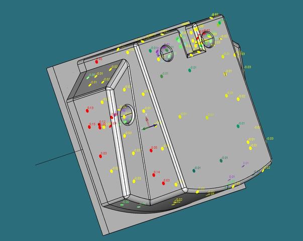
3D in reporting
Option to make 3d PDF report, based on point-cloud measurements. Same as on image, but in PDF, or something else readable by users who don't have pcdmis.. Maybe export as step model with this measured values. It's much productive to look at measurements by engineers, and it's easier to create report (for complex models) instead of cad only option.

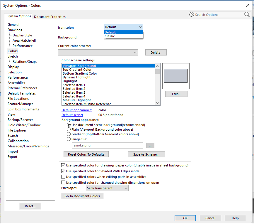
Icon Color Option
SoildWorks added a Icon color option. The option is to be able to change the Icons color from Default to Classic. Maybe they could do this with PC-DMIS to have a Icon color option.
SOILDWORKS 2016 User Interface

Have the ability to change the program from English to Metric, not just the reporting
A button that would convert the programming code from English to Metric or vice versa. If it can be done in the reporting, why can't it be done for the program itself?

Avoidance moves - using both before & after for the same feature
it would be a good idea to be able to adjust BOTH 'before' & 'after' when using avoidance moves on the same feature.for example, you might want a before distance of 40 but an after of 80.
Simulated run time of CMM
ability to estimate quickly the run time off cmm.
For resources planning and system usage
Customer support service by UserEcho
