Hexagon Measurement SystemsNo matter what Hexagon measurement equipment or software you use, we want to hear your ideas and suggestions on how we can improve.
Thanks for your assistance in helping us shape the future. |
|

 Probe head B angles only
This is a hardware request only.
I'd like to have a probe head with only B angles for rotation of star probes.

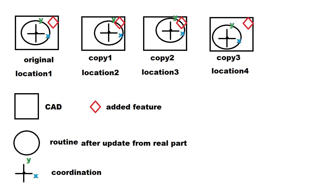
copy and paste with pattern that CAD would be pasted the same way as routines.
once the routine is programed on original CAD, the copy and pasted procedure should include an option that "want to copy and paste CAD" the same way as routine so that CAD would be synced with routine. with this way, it would be easy to modify or add feature based on current run. for now after running all parts with pattern (many parts on a fixture), if i go back to add one feature on CAD number3 for example (CAD number 1 is original) at location 4, coordination of new added feature would not be correct anymore because CAD number 3 is not synced with the routine at that location, location 4. at location 1, CAD would be synced with routine but not other locations. thus it would be a big improvement on "copy and paste" if CAD and routine can sync automatically any location.

Circle Line Intersection improvement
Introduce a toggle command that will:
Allow a circle to mathematically grow until an intersection occurs inside of the intersection command.
Allow a threshold limit to be applied.
What this fixes/allows:
For example my circle is obviously tangent to a line. The 3 points i utilized for my circle were erroneous and my circle calculated a few microns smaller than actual due to form error. The circle is still obviously touching the line. In this scenario I could allow a threshold of .05mm to control my form error - PcDmis calculates the size needed to intersect the line and TEMPORARILY applies that size in the intersection command. Allowing me to reliably program certain edge cases with out a nuisance stop.

Somehow mark Significant Characteristics (SC's) (CC's) on a report.
I would like to somehow make all the Significant Charateristics stand out of the report without moving them out of balloon order. For example.. F1, F2, F3(SC), F4, F6(CC)....

Default setting of the calculation type of the elements
Currently, an elemente open always with the setting of the last use.
But since most of the time is the default setting ASME or ISO 1101, it would be an advantage if this be can adjusted in advance.
I would suggest here to insert an pullup meneu in the menu „NEW“ where the default setting of the elements can be preset.
Vision Auto Features - Percentage based enhancement
Currently, when editing settings for vision auto features each segment is given it's own setting, clicking back and forth between options or un-segmenting and editing then re-segmenting is your only option. It would be nice to check all features for editing or just certain features for editing.
Vision Auto Circle - Start/End position enhancment
Currently, if i'm running percentage based vision circles, I have to guess and check between settings to align gears to teeth while maintaining all of the appropriate settings.
Allow the start and end positions to increment simultaneously by a degree while maintaining settings.
Vision Circles - Percentage improvement
Currently vision segments are restricted to manual segmenting or a generic 10% percent based increment.
Problem - Gear circles often have in excess of 20 teeth and percentages do not line up with arc length of given teeth.
Solution allow percentages in increments of 1%
Variable focus - Vision / Focus Plane
It would be nice to support a quick focus where I can set an intial amount of pre-focus at a lower mag then fine-tune the focus in high-mag - in one feature. Similar to re-measure of a circle.
It would also be nice to have a quick focus feature incorporated into an auto plane where either the first point, three points, or all points have that ability. Rather than multiple alignments, several times.

Сервис поддержки клиентов работает на платформе UserEcho
