Hexagon Measurement SystemsNo matter what Hexagon measurement equipment or software you use, we want to hear your ideas and suggestions on how we can improve.
Thanks for your assistance in helping us shape the future. |
|

 Add function to AUTO CYLINDERS
add ability to AUTO CYLINDER to generate TO CIRCLES similar to TO POINTS

List angles outside CMM volume during collision check
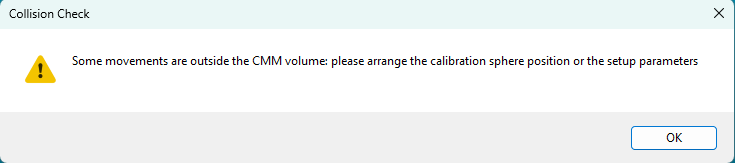
Is it possible to have the program list the angles that are outside the volume during collision check? Something like
Movement T1A90B90 --> T1A0B90 [ Out on X, Ok on Y, Out on Z ] ?
I know you can have the program automatically calibrate angles for you, but I have had situations where ramming into the checking sphere with the head then rotating to an already calibrated angle was the programs way of avoiding collisions ... did it twice. Anyway, due to that, I have been manually picking the angles. The problem is I have 18 angles. I put them in an order that should theoretically have no problem with transitioning from one angle to the next but when I hit collision check, I am met with this generic message that could be more helpful.
I would also like for it to stop marking all my angles as uncalibrated and removing my order only because collision check failed... but that's a topic for another day.
being able to see the report window (as the part is running) in the inspect application.
Having the ability to see the report window while the report is running or even the edit screen while the program is running in Inspect would help us determine where in the program a fault occurred. All we can see currently (In 5.1) is the CAD, %, and pass/fail screens

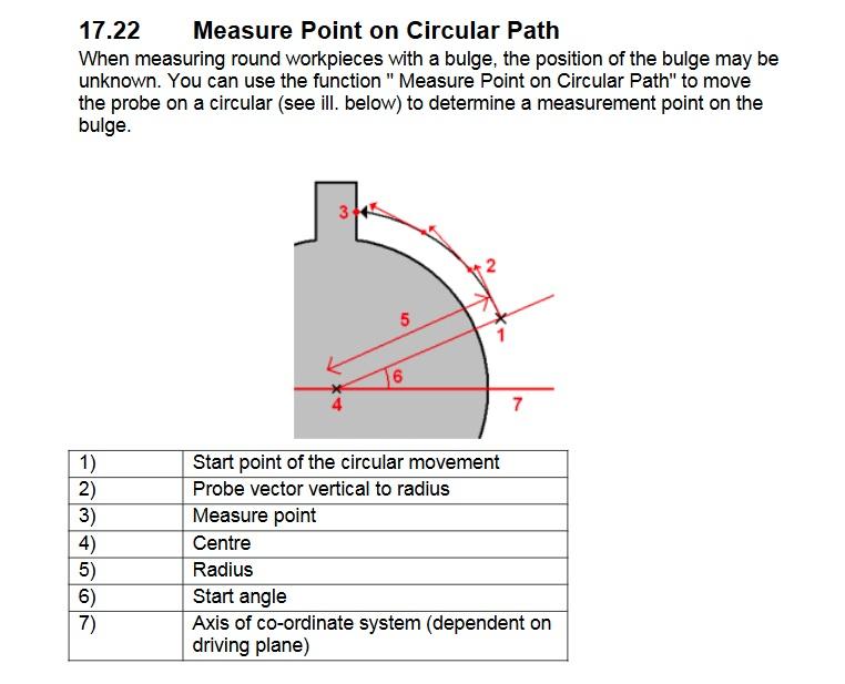
Measure point on circular path
M-Cosmos/Geopak (Mitutoyo) can measure a point on a circular path. This is useful in certain situations when rough aligning a round part or when the rotation of a radial feature is not necessarily clocked to other features on the part.
See this forum post for more details/examples...
PC-DMIS forum "How to search for point radially or using circular moves"
Here is the example from M-Cosmos/Geopak help file...

FIX some elements to not be shown
During programming, it is convenient to hide the elements using the 'Hide all elements' function.
Then, when creating dimensions, you can select the elements to be measured by choosing “Show all elements”.
However, it would be useful to have the option to prevent certain elements, such as manual or automatic alignment elements, from appearing again.

Change the dimensioning Location, Angle, and Distance commands to behave like the Geometric Tolerance windows
The Geometric Tolerance windows are able to self-filter as you type in feature names, which I appreciate because it speeds up the dimensioning process.
Though the Location, Angle, and Distance commands - they still behave like legacy, although they are also still widely used.
The search function on these is cumbersome - why not update it to behave like the Geometric Tolerance search list?


Input comment text size setting, especially when using full screen input comments
I'm currently developing Pc-Dmis programs to be used in production. We typically have operators that run parts on up to 4 cmms each - they're performing setup (no manual measurements), loading parts, following prompts and printing reports only. We utilize bar code / 2d matrix scanners, and when the operators have to enter data into an input comment either manually or with a scanner they cannot easily see the text that has been entered. We use full screen input boxes for user input. I do have some programs that have forms, but I am currently the only programmer at our facility that knows how to create them. Would it be possible to add a text size control (full formatting would be awesome, just like on the forum I'm using now) to input/comment dialog boxes?

Window Boundaries need to respect available desktop
When using multi monitor ALL windows within the PCDMIS software should respect available desktop work space and not be allowed to appear off screen, also there is a bug in 2025.1.112.0 where defining the "main display" causes Auto feature window to appear off screen depending on the display chosen.
Point density via count vs per mm/in
The ability to simply plug in the amount of points i want for a strategy vs amount of pts/mm would be useful as to not plug in a number that bogs the software into eternity.

send tip data to report
ability to send tip data (name & date/time they were calibrated) to the report
Customer support service by UserEcho
