Hexagon Measurement SystemsNo matter what Hexagon measurement equipment or software you use, we want to hear your ideas and suggestions on how we can improve.
Thanks for your assistance in helping us shape the future. |
|

 Offer an option in the installer for Language Pack installation
It often happens, that the user forgets or omits to install the Language Pack. The local AE’s told me that it will be helpful if during the installation (probably last step) the installer requests to indicate the location of the Language Pack (you should allow to skip, but at least the user is warned that the language pack has not been installed).

Feature Point Display Symbol size default to tip size.
Have the feature point symbol default to the current tip size. Handy if you are working in tight spaces. Probably should retain the ability to make it whatever you want; just add a current tip size check box. I know you can change it in CAD and Graphics setup/ Symbols but I'm lazy...... :)

Create folder if not exist
It would be great to add insert folder. The solution with scripting is much too difficult for users.

Parameter Editor Dialog Window
Hexagon needs to create a Dialog window that a programmer can change Parameters in the Edit window. With this dialog window a programmer would be able to edit parameters for individual features, selected features or all feature parameters.
Example how a programmer can Highlight Labels in the Graphics window with the Edit Feature Appearance window.
There was also a Global Update program that would change the Parameters of Features and Dimensions. There is an example VB program that is installed with PC-DMIS the Data Field Edit that can edit more than the parameters.
Link to the PC-DMIS forms

Add a hot key to toggle #1 Clip Plane on and off
Add a hot key to toggle #1 Clip Plane on and off.
Currently this is a 4 click process.


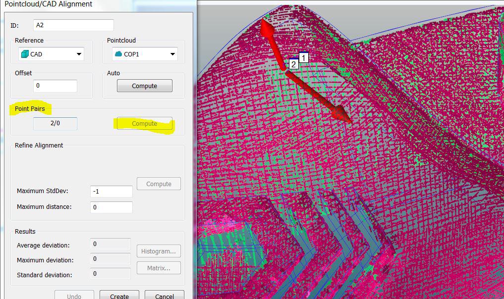
Change marker size
Ability to change the marker size to bigger when you click on the point cloud (Point Cloud Alignment). Often you click straight through the cloud then you select points.
See this two points, they are clicked very close and one is going thru the top surface on my cloud.
Of course I know the alt- buttom ;-)

Representing size dimension in report window
Most engineering carries specification for size mostly one time whatever the feature may be. There wont be specification separate for upper and lower size's . The fitted geometry would result in multiple size evaluations as specified by the size operator. It looks good if the size reporting carries max and min sizes in a bracket in the reporting window automatically as we are representing the nominal twice in the report window with positive and negative dimension. This could better be single nominal dimension with clear explanation of measured sizes represented as per the specification operator's.

Ability to define "paste with pattern" offsets by CAD selection
Title pretty much says it all. I've got a CAD model right there in the CAD window. I'd like to be able to define pattern offsets by clicking on CAD geometry.

Having ability to choose the alignment in which values of assignments are given
For example, ASSIGN/V1=QUALTOOLDATA("XYZ", "MY_SPHERE") or ASSIGN/V2=PROBEDATA("vector") are given in STARTUP alignment whatever the actual alignment.
If I want to use them in a prog, I have to recall startup, then create a generic feature and recall the actual alignment...
It would be more simple in actual alignment !
Customer support service by UserEcho