Hexagon Measurement SystemsNo matter what Hexagon measurement equipment or software you use, we want to hear your ideas and suggestions on how we can improve.
Thanks for your assistance in helping us shape the future. |
|


 2d overlay import with vision
allow for a post alignment import of a dxf to overlay the part in the vision window for real time viewing

size error with narrow autofeature cylinder.
When measuring autofeature cylinders either ID or OD scanning or analogue TTP or extracting into a point cloud PC-Dims cant calculate the size UAME / Local and gives an error. We have many parts that have 4 to 5 MM wide grooves for seals that have ~.050-.008 mm diameter tolerance and we need to see the UAME and Local measurements. ASME Y 14.5 -2009 requires that "Unless otherwise specified, all tolerances apply for full depth, length, and width of the feature."
for Hexagon review see Case # 00723032

Datum OSP compensation as a datum modifier, need the ability to shift Datum to compensate for coatings.
Need the ability to easily compensate a set value per Datum, if a Datum surface is going to be anodized we need to compensate for the coating thickness, if you add a modifier to do this similar to the Unilateral Tolerance modifier it would save a lot of thought, effort and alignments to compensate for this while needing a separate program for pre and post OSP with these compensations. With this modifier we could just remove the modifier or change the value to compensate.

Add option to click on Feature in Pattern Setup
When in Pattern Setup add the option to click on a Feature to automatically fill in the offsets or center of rotation.

Radius True Position
What is the proper way to report a True Position on a Radius?
If "display as radius" is selected, the True Position is cut in half.
Example, If I measure the feature as a diameter the True Position is 0.6 but if I select "display as radius" the True Position is 0.3

part programm shifting size
Size Shift
Write a program and then use it for 3 larger parts without having to recreate it.
Enter a Shift/Magnification factor and the other programs will be adjusted automatically.


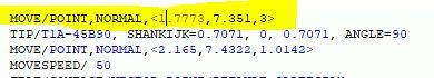
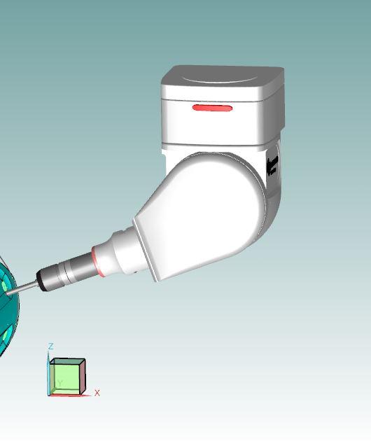
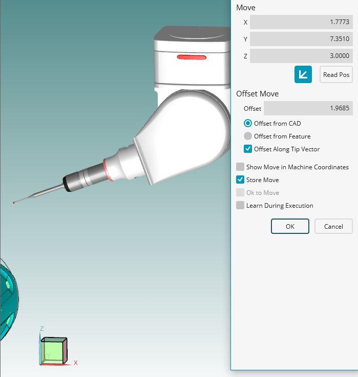
Move command visualation
It will be more usefull if we can see the move point command visually. We need to press F9 (edit window) to see where will probe move.
1. picture: coordinates of the move point
2. picture: before pressing f9 probe's location
3. picture: after pressing f9 (edit window) true position of probe.
It will be more faster way to see which way probe will move.

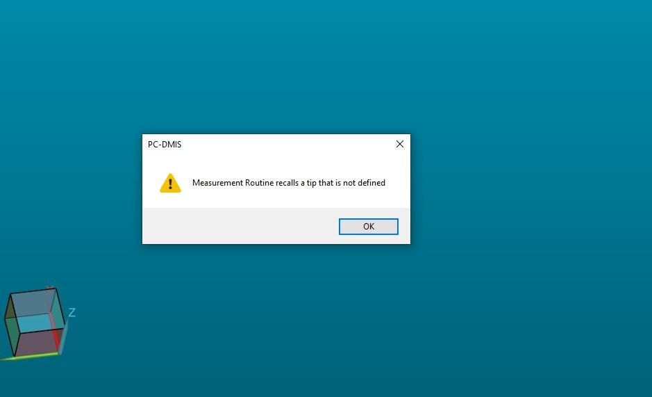
Button for non-calibrated angles
My machine has a tool charger that has eight tools. When I start the program from the server, the program tells me that I have some angles that are not calibrated. I then have to manually search the program and calibrate tool by tool. After that I have to exit the program
and to enter again to make sure that I have calibrated all the angles. It is necessary to put a button that, with one click, will mark those in the head that are not calibrated without exiting the program.
Customer support service by UserEcho