Hexagon Measurement SystemsNo matter what Hexagon measurement equipment or software you use, we want to hear your ideas and suggestions on how we can improve.
Thanks for your assistance in helping us shape the future. |
|

 Feature vector arrow size
When programming a large radius with a shorter angle, the vector arrow scales up with the radius size blocking the edge so you can't see where your hits are located. It appears to be based on the feature size. Working with tech support and a developer on Case # 00264120, they confirmed it is based on feature size.
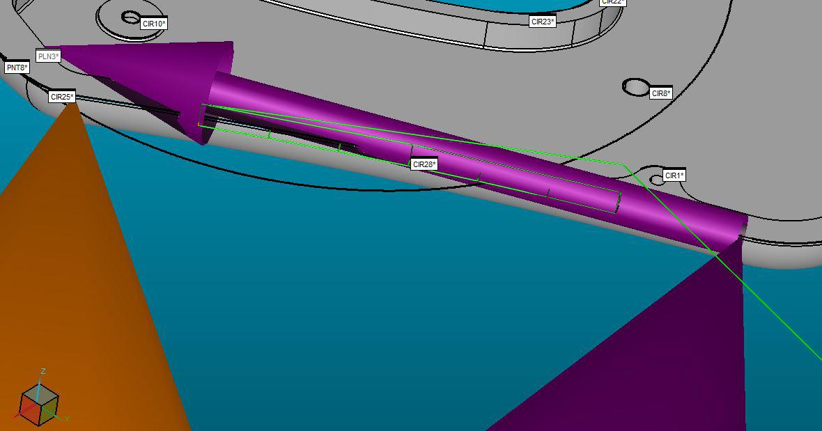
I would like to be able to decrease the size maybe through: Edit - Graphic Display Window - Display Symbols. Please let me know if you require additional information.
Thanks in advance for the help.

Place an LED light across underneath of bridge to illuminate the work area.

composite default datums
Currently when creating a composite or multi-tier dimension the second and following tier datums are displayed in alphabetical order. By definition, with composite tolerances, the datums have to repeat what is in the first tier in the same order. On the second and following tiers, the programmer should be able to just click on the datum + symbol and the corresponding datum from the first tier should appear. If for some reason the programmer needs to deviate from this, they should use the custom check box.
I'm at Datum AR on my current project. Way to much scrolling back and forth.
While I'm at it, the + symbol to display the composite option check box should be more visible. Dark Green with a thin black symbol is hard to see on my 43 inch 4k monitor. (Another example of my general difficult to find things in toolbars rant.)

Add a "work plane" selection to the new Pattern Setup
You could be in the Z workplane but want to create a pattern relative to the X or Y workplanes
Add jump hole to the adaptive cylinder and circle scanning
Add jump hole to the adaptive cylinder and circle scanning in auto feature.


Ability to adjust the vector of an avoidance move
In addition to being able to separately adjust the distance of avoidance moves, it would be nice to control the vector of an avoidance move.

CREATING A WIDTH AUTOMATIC USING THE AUTO SLOT MEASURMENT
If I can create a slot or a circle relative to a plane than why can't I create a width in the same manner. Why should I have to create additional alignments. Example: I have a project that has 60 slots most of which are used as datum features. Creating 120 widths and 60 additional alignments in a program is not practical. Secondly, Why can't I use the points that make up the auto slot measurement and have pcdmis create widths using those points automatically ? Something else to consider is that all of these slots are drafted with no parallel sides.

Inserting a feature into an argument list
Inserting a feature into the beginning or middle of an argument list, PC-DMIS doesn't parse the string as it's pasted and thinks the existing name is getting lengthened, even if a comma is present. When creating a FEAT/SET, I needed to include individual hits. I started with the dialog box and selected PNT3. It needed to be the 3rd point in the list, but it was the easiest to select. The feature set was:
CONSTR/SET,BASIC,PNT3,,
Then I was told I needed to change it so it explicitly brought in the single hit
CONSTR/SET,PNT3.HIT[1],,
Then I needed to add the first 2 points from LIN_L in front of it in the list
CONSTR/SET,BASIC,LIN_L.HIT[1],LIN_L.HIT[2],PNT3.HIT[1],,
But this didn't squeeze 2 additional points in front PNT3. Instead, it changed the name of the single argument to 'LIN_L.HIT[1],LIN_L.HIT[2],PNT3.HIT[1]'. This behaves the same whether I paste the new names as strings, the them manually or use a combination of both.
It appears that PC-DMIS doesn't recognize the commas as delimiters when it's re-parsing the line after an edit. And it doesn't change the quantity of arguments unless the additions are at the end.

excel form report keep the Excels formatting/allow tables.
currently Excel form report clears out any formatted cell where the data will generate. Can we have it so it doesn't clear out the cells formatting or so the information will generate in a table inserted into the excel sheet.
Customer support service by UserEcho